|
|
Sport Compact Car - February '98Project 200SX SE-RBy Mike Kojima [Put into HTML format by Mike Mager] The quest for clean power takes us to the cylinder head. Join us as we take a look at the art of head porting, and take our head to DPR to watch an artist at work. PHOTOGRAPHY: Dave Coleman, Mike Stute Since we tackled the basic engine modifications in the second installment of project SE-R (SCC, July, '97), we now are getting into a slightly more involved mode of tuning. In the search for more power while keeping the watchdog OBDII system happy, we turned our attention to the cylinder head. Ok, the cylinder head is techinically a bolt-on, but the work that goes into it is far beyond what we have done so far. Achieving good airflow through the cylinder head is essential for creating power. Basically an engine is an air pump. To create the most power possible, it is important to make it possible to get the maximum amount of air into and out of the engine with the least amount of effort. Excess intake and exhaust port restriction makes getting air into and out of the engine more work. This extra work is called pumping loss. Imagine sucking a real thick milkshake through a thin straw. This takes a lot of effort on your part. Now drink that same milkshake through a larger diameter straw! The extra effort you are expending to drink that milkshake through the thinner straw is a pumping loss.
Pumping losses have a direct effect on volumetric efficiency. Volumetric efficiency is the percent of an engine's displacement that is filled on each intake stroke. Let's say that you have a cylinder that displaces 1000 cc's. If the engine can take in 800 cc's of air on the intake stroke, your engine has 80 percent volumetric efficiency. Eighty-percent volumetric efficiency is close to typical for a mass-produced naturally-aspirated engine. Going back to the milkshake analogy: Let's say that after 10 seconds of drinking with the wider straw your stomach is full. If you switched to the thinner straw and drank with the same effort, you would only be 50 percent full. This would be analagous to 50 percent volumetric efficiency. A stock engine's port size and configuration is carefully calculated by the factory to be close to optimal, however, when an engine is modified for more power, the flow demands of the engine also change. Air intakes, headers and cams that demand higher rpm operation demand more flow. More flow often requires bigger ports with more cross-sectional area. Imagine drinking that thick milkshake through a straw twice the diameter; it's much easier right? That is the effect of porting-- it reduces pumping losses and increasing volumetric efficiency at higher rpm. In cylinder head porting, the intake and exhaust ports of the head are carefully reshaped by hand. They are enlarged and streamlined to reduce pumping loss inducing restrictions to as low a level as possible. Porting involves extensive hand finishing to remove tooling cuts, sand casting pits, and lumps and bumps made by the mass-production tooling of the factory. Keep in mind, except in rare cases like the Integra Type R, heads are not ported by the factory, as it is much too labor intensive and expensive. Porting, as with most high performance modifications, has its limitations. It is possible to make your ports too big. An amateur cylinder head tuner will simply hog the ports out, making them as big as the Holland tunnel. Big ports can flow big numbers, but big flow numbers alone will not make big horsepower. Larger ports have a lower velocity given the same flow demand. An air column of a given mass at a lower velocity has less inertia, negating any ram effect. The ram effect is critical for obtaining complete cylinder filling at low rpm. Incomplete cylinder filling at low rpm causes an engine to have poor low-rpm power. A symptom of excessive porting is a soggy bottom end that only makes horsepower in a narrow, few-hundred-rpm range at high-rpm. Ports that are way too big will make significantly less bottom end grunt, and perhaps even less power than a stock head at high rpm. In carbureted or throttle body injected motors, oversize ports with low velocity can cause poor fuel atomization with its attendant bogs and stumbles. Typically, an engine with overly big ports, a high performance camshaft and a carburetor will barely run at low rpms. Going too big in the ports can also mechanically weaken your head to the point where it flexes, blowing head gaskets frequently or even causing cracks. The main trick to effective head porting is making the "straw" wide enough to feed your thirst but not so large that you can't suck hard enough to bring the milkshake to your mouth.
Truly effective porting is artwork. There are no hard and fast engineering rules that can be applied to all cylinder heads. A good cylinder head artist tries to shape the port to get the maximum flow with a minimal amount of enlargement, and keeping the velocity high a priority. Most good cylinder head tuners have their own closely guarded shaping secrets for finding the magical diametric combination of high velocity and high flow. In NASCAR, CART and Formula One competition, port shape is one of a team's most highly guarded secrets. Another important aspect of headwork is the valve job. Believe it or not, up to 50 percent of the flow gains generated by good headwork can be found in the valve job. Factory valve jobs usually involve the cutting of the seat, (i.e., the valves that seal to a 45-degree surface). Sometimes there are additional rough cuts made to the port to ease the air's approach angle to the valve. This is why factory valve jobs are usually either called one or two angle; one angle being just the seat surface, two angle being a seat surface plus a smoothing throat cut. In a cost conscious, mass production environment there is simply no time or money to spend on small details like a multi angle, precision valve job. If more flow is deemed necessary it is usually cheaper for engineers to spec a slightly larger valve. Wide seating surfaces are more forgiving to mass production mismatches, which provide good sealing for the life of the car even with a significant misalignment of the seating surfaces. As valves and seats wear, they tend to sink lower into the seats creating seating surface mismatches and valve shrouding (partial blockage or restriction caused by objects in close proximity or forcing the valve to lift itself out of a deep crater before it can start to flow). Wide seating surfaces tend to last a little longer when the valves sink under wear, and long life is an important design goal on production engines.
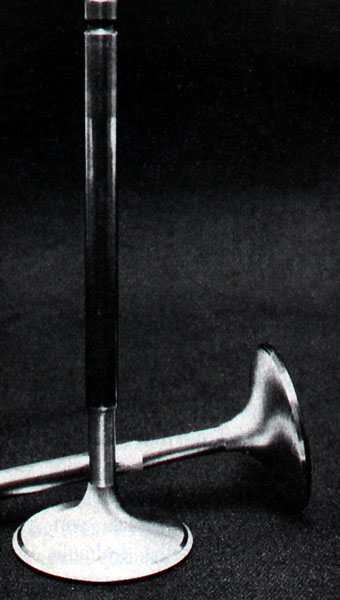
On a mass production engine, due to wide production tolerances, the seat cut is much wider than actually needed. With the valve seat width at a minimum and having the seats matched to the valve, the incoming air or outgoing exhaust has less restriction due to the unshrouding effect this matching produces. Simply put, as the valve moves away from the seat, more area for flow is exposed sooner. The third and final cut is called the top cut. The top cut is generally about 20-30 degrees and is made immediately after the seat. The top cut also helps reduce valve shrouding of the airflow past the valve (or before, as in the case of the exhaust valve) as the valve starts to lift off of the seat. Sometimes a head tuner will make a five angle valve job, adding additional cuts to make the entrance and exit to the seating surface even smoother for airflow. The very best valve jobs are called radius valve jobs. A radius valve job is a five angle valve job where the two angles adjacent to the valve seating surface are hand blended together, into the port wall and combustion chamber for a totally smooth transition from seat to port to combustion chamber. These valve jobs are very labor intensive and therefore very expensive. Another trick to increasing flow is to have an approximately 30-degree back cut on the valves away from the seating surface. This also aids in unshrouding the valve to airflow as the valve starts to open. Opening and low lift flow are critical to making lots of horsepower because the valves spend more dwell time at low lifts and opening than at full lift. In simple terms, the valve is only fully open once per intake or exhaust cycle, but is near the seat twice as much as the valve has to both open and close! That is the primary reason why a simple valve job can make so much difference in flow and horsepower. Unlike most high performance mods where bottom end performance is robbed to get better high-end power, valve jobs fall into the free horsepower category. Enlarging the ports can often compromise low rpm performance as explained in the previous paragraphs. A high performance valve job, however, can increase power throughout the powerband with no sacrifices or drawbacks of any sort (except cost and perhaps long term durability as the narrowed seats tend to wear a little faster). Street high performance valve jobs usually have a little wider seat cut for longer life, although some head tuners dispute the idea that narrow seats wear any faster. Modern multi-valve engines usually have hardened valve seats for unleaded gas use and run lower valve spring seat pressures than old-school V8s, so valve seat wear is lower and seat width is not as critical for long term durability.
The exact valve angles used by cylinder head artists are another closely guarded secret. The angles and techniques listed here will vary from one cylinder head specialist to another. This article is an attempt to explain some of the more general and common techniques used to modify cylinder heads. To successfully modify the cylinder head on an OBDII-equipped engine, extremes must be avoided. Huge ports and valves can cause such a significant reduction in intake flow velocity that back flow in the ports can occur more easily during the overlap period of the four stroke cycle. This back flow or reversion, as it is called by engineer-types, can cause several different problems. The effects of reversion are more pronounced at idle and low rpm due to the already-low port velocities under these conditions. Severe reversion can play havoc with airflow meter readings. If the airflow meter voltage fluctuates out of the OBDII's allowable window of operation, a failure code will be triggered. Reversion caused by large, low-velocity ports can make the loping idle of a hi-performance camshaft more pronounced. This can cause irregular readings from the crank angle sensor making the OBDII system trigger failure codes. When an engine lopes, it is misfiring due to charge dilution and eight stroking as explained in our first engine article. Since detecting misfires is one of OBDII's responsibilities, the system would only be doing its job if it triggered a trouble code. Eight stroking can also cause an engine to run rich at idle. This can cause the O2 sensor to read at too high a voltage at idle which will also trigger a trouble code. To correctly modify the head of an OBDII equipped engine, close attention must be applied to keep the overall port volume small. Since simply increasing the overall diameter of the port is out, careful re-contouring of the port to improve flow without sacrificing velocity is essential. More flow can be picked up through the careful re-cutting of the valves and valve seats without risking error code triggering.
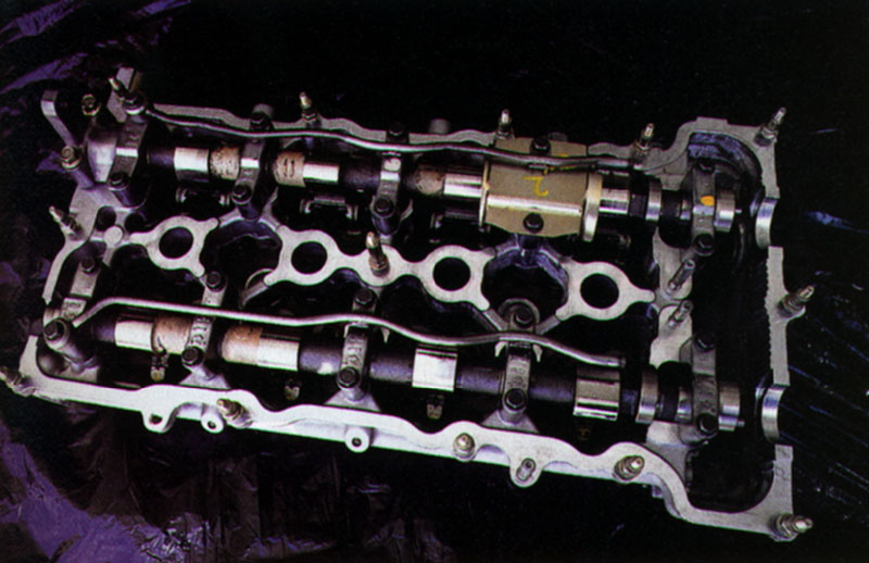
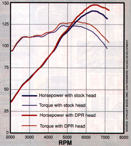
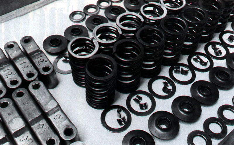
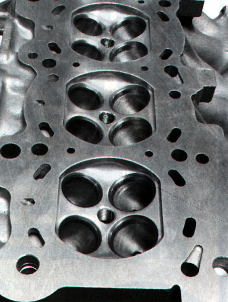
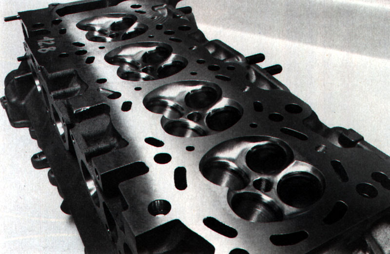
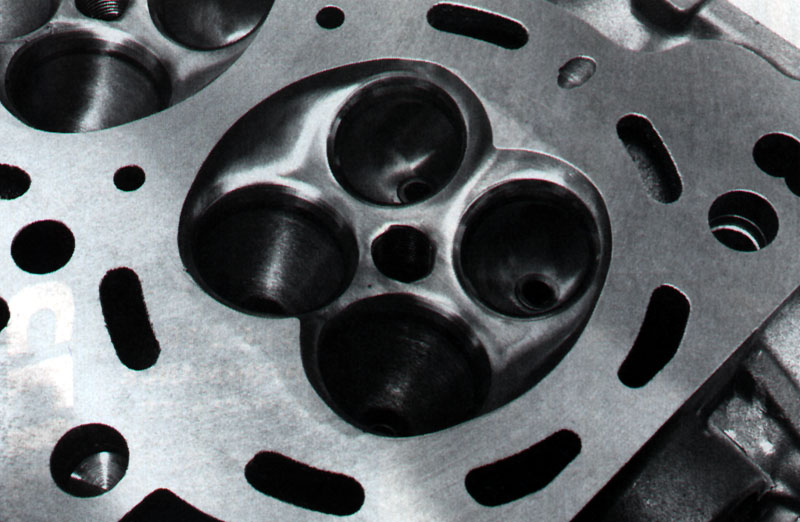
To handle the head work for Project 200SX SE-R we went to Dan Paramore Racing Development (DPR) of Torrance, California. Dan Paramore has handled head work on some of the extremely-fast factory-sponsored racecars, including the Toyota Eagle IMSA GTP car. He is also the man behind many of those 12- and 13-second all-motor, pump gas burning, daily-driven, naturally aspirated Hondas and Acuras. Paramore's facility has a complete engine and cylinder head machine shop capable of anything from simple racecar maintenance to total engine building. DPR uses a Superflow cylinder head flow bench that is essential for accurately measuring improvements during port shape and valve angle development. DPR also has a state-of-the-art Dynojet inertial chassis dyno which we have been using to monitor our gains through different stages of the build-up on the SE-R. DPR normally offers headwork in stages one through six. Stage One being a basic precision multi-angle valve job, with Stage Six being a full-race prepared head. After carefully studying our Nissan's cylinder head Paramore drew up a plan of attack. Unlike most of Paramore's customers, who only crave raw power and speed, we care about passing smog tests and avoiding telltale error codes stored in our ECU. This challenge actually makes Paramore's job even harder as he has to consider the elimination of reversion, the maintenance of high port velocity at idle and small throttle openings in addition to getting the most peak flow. Because of the many restrictions on port size imposed by the OBDII system we were not expecting as much peak horsepower as DPR's full-race, all out Stage Six head. We simply hoped for a broad useable powerband instead. Many of the details that Paramore showed us were proprietary, and to protect his secrets he asked us not to give more than a general description of what was done. DPR pays extreme attention to small details in the preparation of a performance cylinder head. Dan first carefully stripped the head, taking note of critical dimensions such as valve tip height and adjustment shim thickness to assure proper dimensions during assembly after all the work is done. Due to Nissan's cam follower design, it is critical that the original clearances have been maintained to preserve valvetrain geometry. The wrong shim or clearance here could result in noisy valvetrain operation and extremely quick wear. After disassembly, the head was cleaned and carefully deburred. Cartridge rolls were used to remove casting flaws that could induce stress-risers and to remove any possibly entrapped casting sand from the surface of the head. All threaded holes were inspected and cleaned out with a tap to insure easy assembly. Finally the head was washed and made ready for some serious work. After de-burring, Dan welded up the quench pads of the combustion chamber. These are the flat edges on the sides of a four-valve pentroof combustion chamber. The advantage here is threefold. Increasing the quench area of a combustion chamber increases the amount of turbulence in the chamber as the piston comes to TDC on the compression stroke. This creates a more homogeneous mixture of fuel and air throughout the chamber for a more even burn. The additional turbulence also speeds flame propagation. These factors make for more efficient combustion, aiding exhaust emissions, fuel economy and power. In adition, quench area makes the chamber more detonation resistant. Since we are running nitrous oxide, detonation resistance is important for engine life. The reduced surface area to volume ratio, complete high-turbulence burn, and the low unheated wall area of a compact combustion chamber can also reduce hydrocarbon emissions. Increasing the quench area with this welding technique also raises the compression ratio; a long time standard hot rodders. Raising the compression ratio increases the thermal efficiency of an engine. These increases of thermal efficiency caused by raising the compression ratio and increasing burn efficiency usually lowers hydrocarbon emissions, but can diametrically increase oxides of nitrogen and carbon monoxide output. Strangely, these noxious pollutants are the byproduct of a clean-effect burn cycle. Fortunately for us, modern three way catalytic converters are quite efficient at removing these bad boys from the exhaust stream. Finally, increasing quench causes the fuel-air mixture around the circumference of the combustion chamber to get squeezed in toward the center by the rising piston. Because it is now flung toward the burning fuel around the spark plug, this fuel is now burned in the combustion process. This creates a more complete burn, more power and higher fuel efficiency. The only drawback to increasing quench is more crevice volume, (the small crack between the combustion chamber and piston dome as well as the top of the piston to upper compression ring) which can increase hydrocarbon emissions. This is because the small quantity of fuel and end gasses trapped in the crevace area doesn't burn and can be expelled out the exhaust. In our case, we think that our catalytic converter has enough oxidation capacity to correct this, but we will watch the hydrocarbons closely because they can be detected by the dreaded roadside smog machine. After welding, Paramore surfaced all of the sealing surfaces of the head, including the combustion chamber, intake, exhaust and valve cover faces to insure leak free operation despite any distortion that may have occurred during welding. Paramore then hand contoured the combustion chamber to obtain a cloverleaf configuration. This shape was used by Chevrolet in the multi-valve Corvette ZR-1 engine to get a motor that could run at light loads for short periods of time on 87 octane fuel with an 11:1 compression ratio. Dan set the combustion chamber volume at 43cc's down from the stock 46cc's to give us a compression ratio of 10:1; up from the stock 9.5:1. If we were only going to naturally aspirated power (without nitrous oxide) we would have gone for 11:1, but having a healthy nitrous system we wanted to be a little on the conservative side. Paramore then ported the heads using a die grinder with assorted rotary carbide cutters to optimize flow, but still keep overall port diameter and volume small, because, as mentioned earlier, this is not an all out race port job. He removed much of the support boss for the hydraulic valve lash adjusters which protruded downward and blocked much of the intake port. The early SR20 motors found in the 1990-1993 SE-R and Infinti G20 had the intake port travel smoothly around the hydraulic lash adjusters. Why Nissan choose to redesign the head with such an awkward configuration, we will never know. Paramore left enough of the boss in place to maintain strength in this area. Paramore also smoothed some rough corners in the port and added some secret contours in the port wall to promote tumble flow, which he felt would reduce reversion and give the OBDII system a hand. On the exhaust side, Paramore re-contoured the valve guides and guide bosses significantly and smoothed out all the rough edges encountered. After the rough porting was done, Paramore finished the ports and combustion chamber by further smoothing them with a die grinder using a mandrel with 220 grit cartridge rolls. Finally, it was time for the valve job. The valve angles were cut with a precision carbide cutter in a Serdi valve machine that could cut all three-valve angles with a single pass. The blade alone cost more than $800, but insures precise concentric valve seats and lead in angles. Many low end shops use conical stones of assorted draft angles, but these wear quickly and must be continually dressed to maintain precise angles. Conical stones also require a great deal of skill to do repeatable matching valve seats. A Serdi valve machine is a super precision, air-railed, floating-center valve cutting machine that makes the task of performing a high-precision multi angle valve job child's play. Because Serdi machines cost more than $20,000, not many shops have them. After the seats were cut, Paramore hand blended them into the port wall and combustion chamber for a smooth radius bend. The intake valves were treated to a radical re-contouring, however, Paramore requested we not divulge the exact shape and seat angles. This contouring can significantly increase flow but not decrease port stream velocity. The exhaust valves were left with a less radical contour, as Paramore feels this can reduce reversion. These small but significant details are what set DPR apart from the typical head shop. After the head was ported and the valve job completed, the head was carefully re-assembled. Shims were used to restore valve spring pre-load that was lost when the valve seats were cut. The valve tips were also faced-off to restore valvetrain geometry. On a SR20 motor, it is essential that these steps be followed correctly to prevent excessive wear and to insure quiet operation. We eagerly reinstalled the head, and returned to DPR for Dynojet testing. While driving the car it was immediately apparent the engine had much better top end. The bottom end and off idle response remained good as well. Throttle response was much better, too, which made the engine feel as if it had better bottom end! After strapping project SE-R to the Dynojet we made several pulls. We had previously tested project SE-R with the bolt on modifications only and had produced 142 hp with a broad flat torque curve. This equates to about 163 crank horsepower, which is close to what we obtained on the Bosch dyno we did out baseline testing on (the Bosch dyno measured flywheel horsepower by first measuring drive wheel horsepower, and then determining driveline loss with coastdown measurements). Other bone stock SE-R's have tested out to have approximately 114-119 hp on a Dynojet. With the DPR head we made 149 hp, or about 172 crank horsepower. We were pleased with the results. There was no loss of bottom end power whatsoever, even right off idle. We achieved a slight increase in midrange (3000-4000 rpm) and a good solid boost of 10 hp above 5000 rpm. In most cases, porting results in some bottom end loss, however, we experienced no bottom end power loss, which is a tribute to Dan Paramore's skill at his craft. If our sole objective was to obtain more power we feel that there would be at least another five or more horsepower to be obtained. We could gain even more with bigger cams that would be necessary to make use of big gains in flow, but the OBDII system would probably not like that level of modification. Newer engines with four-valve, pentroof heads usually do not experience the dramatic gains in power that old school American V8s and older generation four bangers experience with head porting. The newer heads are incredibly good stock straight from the factory, compared to the crude chunks of iron used not so long ago. For newer heads a gain of 10-20 hp is typical, compared to 50-100 hp you might get from a small block Ford or Chevy. Now, we are able to enjoy good clean (emissions wise) fun, while still having gained power and performance. In upcoming installments, we have even bigger plans for the engine, so stay tuned.
Reprinted with Permission |