|
|
Sport Compact Car - August '97Project 200SX SE-Rby Mike Kojima [Put into HTML format by Ken Pratte] In part three, we go looking for huge power increases without upsetting the sensitive OBD-II system. For this tall order there really is only one answer: nitrous oxide. In fact, the new nitrous system makes so much power, it nearly ripped the engine out of the car, forcing us to try a stronger clutch and engine mounts. PHOTOGRAPHY: Les Bidrawn, Dave Coleman, Mike Stute In the quest for yet more bolt-on power without scrambling the sensitive OBD-II system we were faced with a dilemma: how do we get more power and still have a no compromise daily driver? The simplest and most inexpensive alternative is nitrous oxide injection. Many reader already know something about nitrous, so we won't go into extreme detail. But we will tell you that it was first used during World War II as a relatively cheap and safe way to get large amounts of emergency power out of airplane engines for short periods of time.
The nitrous oxide molecule is N2O, or two nitrogen atoms and one oxygen atom. It's that one oxygen atom that makes the power. In the heat of combustion, the nitrous oxide molecule breaks down into separate nitrogen and oxygen molecules. The freed oxygen combines with extra fuel creating more heat and power. The extra nitrogen serves as a buffer, preventing things from burning too quickly! That is the main reason that nitrous oxide is used instead of straight oxygen. For those of you who own an oxy-acetylene welding torch, you know what happens when you increase the oxygen to your neutral flame: you get a cutting torch! That's why the nitrogen buffer is needed to cool and slow the combustion reaction, and prevent meltdown. Think of nitrous as a chemical turbocharger, doing everything a turbo or supercharger does, but it does it through the miracle of modern chemistry. Another cool thing about nitrous is that it is only there when you want it; only affecting emissions, driveabilty and your wallet when you desire. Want 30 mpg? Loaning your car to your little brother? Emissions testing your car? Turn it off! Want to kick some butt? Turn it on. Getting an off-the-shelf nitrous kit and bolting it on usually leads to safe, pleasing results. The makers of nitrous kits rely on their years of experience to supply you with safe and sane jetting recommendations. Nitrous has gotten a somewhat tarnished reputation due to the efforts of those who don't understand it well trying to get more power. Adding too much nitrous and not enough extra fuel, or running with over-advanced ignition timing, will cause extra hot combustion and/or engine pounding detonation. These not-so-nice phenomena work wonders on your engines internals. If you are lucky you will only melt an electrode off your spark plug, unlucky folks fry valves, crack ring lands, hole pistons and pound out bearings. Extremely unlucky or foolish persons find major internal parts of their engine outside of the engine! Getting the right ratio of nitrous-to-extra fuel requires good tuning skills and a good eye for reading plugs. Learning these things takes a while and requires hanging some fried motors under your belt. If you are not willing to pay the dues it takes to become experienced it is better to leave the major tuning to the pros.
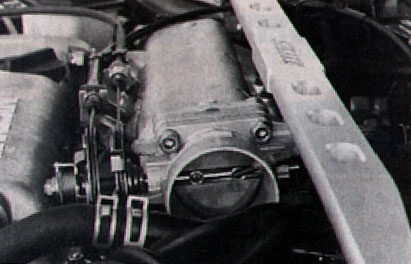
Since project SE-R is a daily driver, we were not willing to take major risks with an insane 11-second quarter-mile bottle rocket special. Our goal was to use high-tech electronic controls to safely contain the largest safe shot of nitrous possible. The natural choice in obtaining these goals was to seek out the two most experienced people in the field of nitrous systems and Nissan electronic tuning, Jim Wolf Technology (JWT) and Nitrous Oxide Systems (NOS). Jim Wolf and Clark Steppler, the masterminds at JWT informed us that with the strong internals of our SR20DE engine, up to 100 horsepower on pump gas was a realistic possibility. The kind folks at NOS provided the basic nitrous plumbing components of JWT's nitrous system. We would be using NOS's basic equipment: bottle, heavy duty cheater solenoid, fan jets, braided stainless lines and switches. JWT would provide the NOS controller. The heart of JWT's nitrous system is their sophisticated nitrous control ECU. The nitrous control ECU uses, in addition to the normal JWT POP chip (Performance Optimized Program) a digital high-speed nitrous co-processor module which contains a ROM (Read Only Memory) chip with a nitrous optimized program and controls for the nitrous solenoid. The secret to JWT's nitrous systems safety is the extreme degree of control this system provides. The extra processor on the sub-board controls fuel enrichment, spark retard under nitrous, activation points and rpm limit. Every obvious classic nitrous failure mode has been considered and dealt with electronically and automatically. In the unlikely event of an electronic system failure the JWT system will fail soft, not allowing the nitrous to turn on. In the near future, JWT will develop software to enable the nitrous system to have a progressive engagement allowing the onset of nitrous operation to start at a lower rpm and come on gradually, instead of coming on all at once like it does now. Sort of like having a big torque engine in a bottle. If we're lucky, they'll have that done before this project is done! When the progressive controller becomes available, owners of the present JWT system will be able to update their standard controllers to progressive ones by sending them back to JWT for reprogramming. To handle the enrichment demands of 100 hp worth of nitrous oxide, the stock Nissan 259-cc/min injectors were replaced with 370-cc/min injectors from an Infiniti Q45. Since the extra enrichment fuel will be coming through the injectors there is no concern over fuel distribution like there is with the typical single fogger nozzle nitrous system. Distribution problems with the extra fuel usually limits single fogger systems to the 50 to 60 horsepower range on small four-cylinder engines. Because intake manifolds designed for electronic fuel injection were only designed for equal air distribution, they tend not to distribute fuel evenly if it is injected at only one point. Some cylinders run lean and are prone to detonation or overheating damage, while others run rich and don't burn efficiently. More than 60 horsepower typically requires a direct port injection system, with a fogger nozzle for each cylinder. The JWT system injects the nitrous from a single fan jet located in the throttle body. As the liquid nitrous immediately flashes into a gas it will be directed in proper amounts to each cylinder. A side effect of this is that this rapid liquid to gas phase change supercools the intake charge making it more dense, kind of like a chemical cold air induction system. The JWT system is very easy to install: just drill and tap the fan jet hole, mount and wire the nitrous solenoid, mount the bottle, route the nitrous line, add the nitrous control ECU and find an empty stretch of road. No fuel solenoid, no micro-switches and no feed tube cutting and bending operations are necessary.
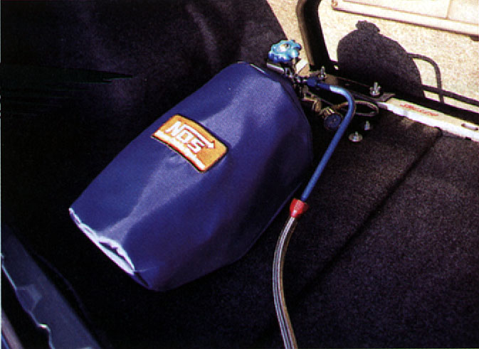
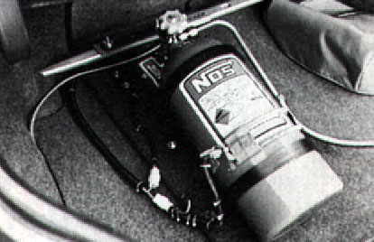
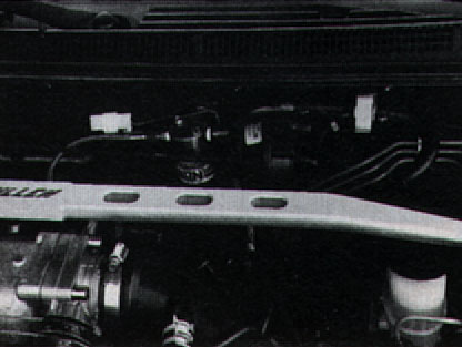
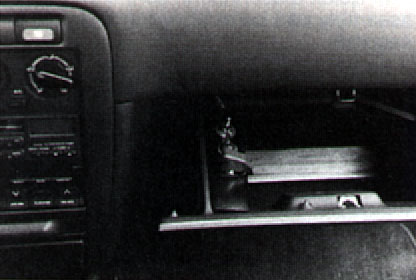
In order to keep the engine from running too rich under normal operation Clark Steppler re-programmed the ECU to compensate for the new injectors. Since the new injectors will respond differently to the ECU’s signals than the stock ones did, the ECU has to be reprogrammed to the new injecor’s specific charateristics. When asked about the exact details of the ECU programming, Clark smiled and said he would be glad to tell us if we agreed to kill ourselves immediately afterwards! What is not secret is how the JWT system works: when the nitrous mode is enabled, the nitrous control ROM on the extra sub-board automatically takes control of the engine at a predetermined safe activation point (4000 rpm in our case). This avoids the possibility of engaging the nitrous at too low of an rpm which can cause excessive and fatal (to the engine and your wallet, not you) increases in cylinder pressure. The automatic nitrous engagement means one less thing for you to do out of the hole and in-between shifts. The JWT controller allows you to drive the car normally without fumbling for the squeeze button. The automatic engagement at over 4000 rpm also helps the car get out of the hole without the tires going up in smoke. The nitrous control ROM says go when the proper conditions for safe operations are present--4000 or more rpm from the crank angle sensor, and a full throttle signal from the throttle position sensor--if these conditions are met, the ROM turns on the nitrous solenoid. As the "on" signal is sent to the nitrous solenoid, the ROM orders the injectors to a higher duty cycle, injecting the required additional enrichment fuel the nitrous needs. At the same time the ROM switches to a spark advance map with less total advance. This functions like the boost retard system that many turbo kits use. The retarded spark helps safeguard the motor from detonation and is also why the JWT system can safely use a big 100 hp nitrous jet on 92 octane pump gas. It is possible to retard the spark at the distributor like many nitrous users do but that causes the car to be sluggish, slow, and to guzzle gas whenever the nitrous is off. The JWT system enables the car to automatically be at a maximum level of tune for both normal and nitrous operation. Another problem many nitrous users encounter is over-revving due to the extended powerband nitrous provides. The sudden rush of power has lulled many a nitrous user to wind it till she blows. The nitrous in a typical port injection kit is controlled by the driver's finger, not the fuel cut in the ECU. The nitrous allows most cars to sail right past the fuel cut built into the engine management program under ham-fisted driving. The JWT ECU cuts the nitrous with the 7700 rpm fuel cut so the engine cannot be over-revved even if you try. To round out the system we added some nice accessories from NOS to make some of the chores of nitrous use a little easier. First off, we added a remote shutoff valve. This is a bottle mounted, electrically-operated valve which allows you to leave the manual shut off valve on the nitrous bottle open when cruising or parking. Without the remote shutoff valve, the valve should never be left open for safety's sake, as a leaking nitrous solenoid could fill the intake with nitrous, causing a manifold to get blown off--or worse--during startup. With the remote shutoff valve the bottle can be instantly opened from the drivers seat if the need should arise. In the improbable event that a nitrous solenoid sticks wide open, The remote shutoff can act as an emergency shut off valve. A safety vent hose was also added to the safety valve of the nitrous bottle. In the event of bottle over-pressure (like an overfilled bottle on a extremely hot day) where the safety valve blows, the nitrous will be safely directed out of the interior of the car through a dash 10 braided steel line exiting through one of the trucks drain holes. Leave the laughing gas at the dentist we always say. The next thing we added was an NOS automatic bottle heater. When nitrous is injected into your engine, it undergoes a phase change from liquid to gas. This causes the bottle to get chilled. The cold bottle loses pressure due to the ideal gas law (which is PV=nRT for those of you who care.) This loss of pressure makes the nitrous system run richer as the bottle empties. This causes a loss of power for each consecutive run. The bottle heater combats this pressure drop by keeping the bottle at a thermostatically controlled 75 degrees. It uses a flexible heater element to heat the bottle during and between runs. The NOS heater has a safety back up thermostat to guard against accidentally overheating the bottle and causing over-pressurization. The bottle heater helps make the engine run much more consistently from run to run. To help the bottle heater, we used an insulated nylon cover from NOS. This cover improves heater efficiency and cleans up the look of the nitrous system. Nitrous systems are jetted to run the best at about 900 psi of nitrous pressure. A glycerin damped pressure gauge from NOS was added next to help determine if the bottle's pressure is sufficient for optimal performance. The gauge will help judge the bottle's filled pressure as a tuning aid if necessary. In case you were wondering, the glycerin is there to damp the gauge's needle, protecting it from failure. Since the car is being built as a multipurpose vehicle, we wanted the bottle and all the associated hardware to be removable at a moments notice; no need to have that 25-pound bottle in the trunk for a road course time trial or a slalom race. We built a simple mounting bracket for the bottle hold-down clamps out of plywood and sheet metal. The bracket securely attaches to the car with wing nuts through the milled holes in the rear Stillen stress bar. We also made a neat wire harness for the remote shutoff and bottle heater, complete with quick-disconnect electrical connectors. Some matching carpet scraps were used to nicely finish off the bracket, matching the trunk lining. Now the bottle is held safely and securely and can be completely removed from the vehicle within seconds.
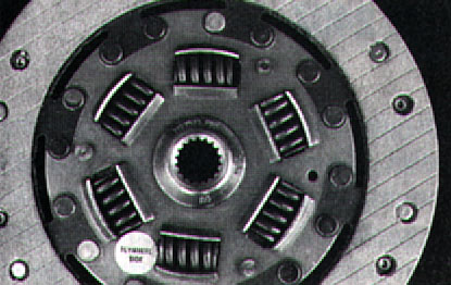
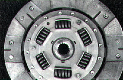
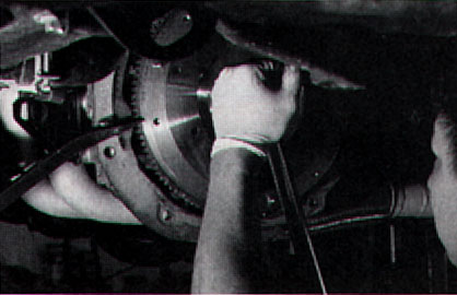
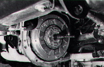
Since the delicate details of OBD-II programming were discussed in Part Two (SCC, July '97) we will not go into it again, but this being the first prototype OBD-II nitrous ECU, we were looking forward to how the system might react to the nitrous on open loop. What we wanted was no retained error codes or MIL (Malfunction Indication Lamp) lights that could cause registration problems or costly dealer visits. Due to time considerations, we were only able to make a few short first and part of second gear passes before packing up to go to Battle of the Imports at LACR. On the first pass we could tell that something was not right; the nitrous was working intermittently or not at all. When the nitrous did work it felt soft, like it was only giving 30-40 hp. The result was a series of disappointing mid-14-second runs, plagued by incredible engine banging, teeth grinding wheel hop upon launching. During a quick trackside call on the cell phone (ah, technology) to JWT, Clark Steppler theorized that electromagnetic noise could be induced into the arming switch wiring. Clark recommended that we add an electronic filter to the ECU's ground loop (by the way, all Jim Wolf OBD-II nitrous ECU's have this filter built in because of this testing). Raiding a nearby Radio Shack we purchased the 10-microfarad capacitor necessary to construct the filter. Steve "Maxboost" Mitchell happened to have his mini propane fired soldering iron handy and we were able to kluge together a quickie noise filter. After adding the filter we found a quiet area in an abandoned industrial park (shame on us) to test the nitrous. The difference was astounding; the car leaped forward, pinning us to the seats. All was right until we threw it into third gear where the clutch responded by promptly frying. So much for the battle. We limped home and made plans to regroup. The next day a call was placed to Chris at Clutch Masters. When we explained our lofty objectives--a clutch with a light pedal and smooth engagement that could be driven daily in bumper-to-bumper traffic and withstand a 100-hp shot of nitrous--Chris surprised us by saying he could do it. He concocted a special clutch and pressure plate combo that actually had a lighter pedal effort while having 40 percent more clamping force. The lighter pedal with more clamping force was achieved by playing with the lever ratio of the diaphragm spring, thus avoiding the typical stiff racing clutch pedal. The clutch disc had a sprung center hub for smooth engagement with Kevlar on the flywheel side and eight ceramic pucks on the pressure plate side for heat resistance and grab. The Kevlar/ceramic disc has the hard-grabbing, non-slip capabilities of a metal disc mellowed by the smooth engagement and high burst strength of Kevlar. One of the unique features of the metal disc is its use of a marcel spring under the pucks. A marcel spring is like a wave washer that gives the friction material some cush before it smashes flat and allows full contact pressure, an important feature in smoothing engagement. A marcel spring is easy to incorporate into a Kevlar or organic disc clutch but very difficult to use on a metal disc. Clutch Masters claims to be the company to successfully use a marcel spring on a metal disc. Clutch Masters also recommended their medium-weight 11-pound aluminum flywheel (the stock flywheel is 18 pounds.) The lighter flywheel would enable better throttle control off the line, and better acceleration while still having enough weight to launch the car and not buck during street driving. The lighter flywheel would also be easier on the synchros and the rest of the drivetrain. The flywheel is a very high-quality piece machined from aluminum billet, with a replaceable steel friction surface and starter ring gear for long life.
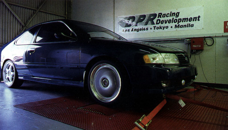
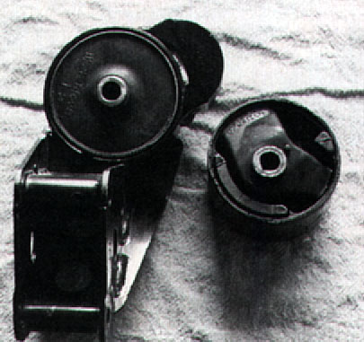
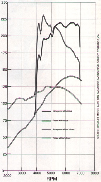
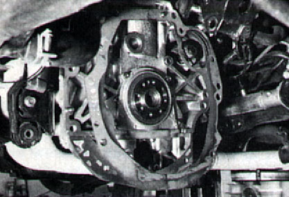
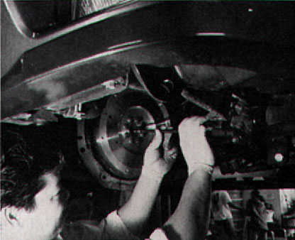
We theorized that the severe wheel hop we had encountered at the Battle of the Imports was due to flex in the soft OEM motor mounts which allowed the engine/transaxle assembly to oscillate back and forth. The oscillations were causing the wheels to get slammed up and down like basketballs. The OEM mounts were designed to make for a smooth, quiet, vibration free cabin, not for launching on a VHT-covered drag strip with big sticky tires. To solve the wheel hop and general engine crashing around under hard shifting and drag racing launches, Jim Wolf Technology came to the rescue again with their heavy duty motor mount kit. These motor mounts do away with the standard flexible engine and transaxle mounts, and are made of a solid rubber-like material. The JWT kit consists of the three main motor mount bushings and one torque control link. The stock torque control link is made of fiber reinforced plastic and allows the retaining bushings to move over half an inch before any resistance to movement is offered. The JWT torque link is made of solid stamped steel with no allowance for any free play before the retaining bushings start to limit engine movement. The solid mounts press into retainers located on the transaxle crossmember, the transaxle case and the passenger side of the engine block. SD Motor Tuning did a quick and efficient job of installing the clutch and flywheel, and Mueller Fabrication pressed in the new motor mounts. During installation we noted that the transaxle case had been beating on the exhaust downpipe and the crossmember. If we had continued to drive hard and launch the car at the drag strip we would have eventually broken some expensive parts. Right after installation, the clutch didn't feel like it had much grab but Chris had warned us not to abuse the clutch until 500 miles had been put on it to break it in. The pedal feel was wonderful, it was even lighter than stock! After a few miles, the clutch disc began to break in and grab. After break-in the clutch had a solid engagement with none of the chatter or excessive grabbiness usually associated with a high-performance clutch. This clutch is actually daily driveable in bumper to bumper traffic. The light flywheel made a noticeable difference in acceleration--especially in the lower gears--and the driveabilty was still decent. The flywheel is not so light that the clutch had to be slipped excessively to get underway. When doing a drag style launch the flywheel enabled fine adjustments of the throttle so that wheelspin could be contained, unlike the stock flywheel where the tires had to catch up with the engine. Heel-and-toe downshifting also seemed easier as the engine now responded to light touches of the throttle. During testing with the nitrous, the clutch has held up very well so far as a few 5.0-liter Mustangs and 5.7-liter Camaros in our area have found out. With the new motor mounts, hard launches are now straight and smooth with no wheel hop. The solid motor mounts do transmit more buzz through the steering wheel, pedals and butt, but it is no worse than a typical four-cylinder pick up truck. The NOS-controlling ECU is also working well, with no tell-tale MIL lights or triggered error codes. If the OBD-II system is kept happy, you will be happy come registration time. When we returned to Dan Paramore Racing Development to dyno our new nitrous system, we found that Dan had replaced the Bosch dyno that we did our baseline runs on with a new Dynojet chassis dynamometer. Since the Bosch dyno measured driveline drag to give flywheel horsepower, and the Dynojet gives drive wheel horsepower, we had to do a new baseline run. On the Bosch dyno, project SE-R made 166 flywheel horsepower. With the same configuration (our current setup with the nitrous off) the Dynojet registered 140 hp at the front wheels. This equates to a 14 percent power loss in the driveline, which seems quite reasonable. With the nitrous on, the SE-R ripped off a run registering an incredible 220 horsepower, and 231 lb-ft of torque. That represents an increase of 80 horsepower and 105 lb-ft of torque. Despite having that handy nitrous pressure gauge, we neglected to check it before testing. When we tried to hit the bottle after leaving the dyno we realized that we had drained the bottle. A dyno run with a fully pressurized bottle should give us even more impressive results! With 220 horsepower and a driveline that can finally handle it, we're looking forward to our next chance at the drag strip.
Reprinted with Permission |