|
|
Installing Cruise Control (A.S.C.D.) in a '91 Sentra SE-Rby George Roffe PARTS LIST:
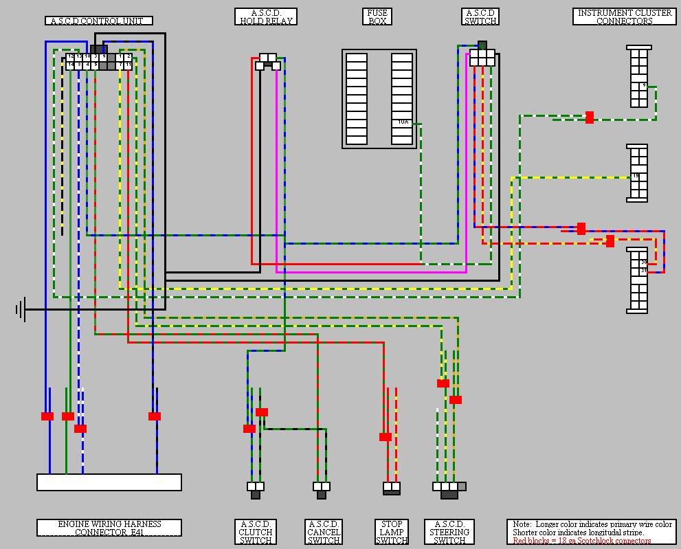
Note: If you don't have one, you really should get an FSM before starting this job. Click here to find out how. No matter how you go about this project, you are going to have to get some of your parts from a donor car that is no longer working. So, you might at well get all of your parts from a car in a wrecking yard or other donor car. Don't worry if your donor car is a XE. A couple of parts are slightly different, i.e the Actuator and the Control Unit. I am using both from an XE. The Control Unit will have a wire for an automatic transmission that just needs to be taped off. The Actuator will have a different cable length. This presents a small problem. You just have to fabricate a bracket to hold the cable. You have to be careful when scrounging for parts in a yard. Cutting a wiring harness is frowned upon. If the donor car is a wrecked car in your (or a friend's) possession, no problem. I did it anyway. Of course, the yard hands cut the harness themselves while removing the radio. The wiring harness diagram has many two color wires shown. The longer color is the primary wire color and the shorter color is the color of the longitudinal stripe. Ignore wires that appear to go nowhere. They do connect somewhere, but you should not be concerned with where for the purposes of installing the cruise control. The lone exception is the black and yellow wire from the Control Unit. This is for cars with an automatic transmission which the 91 SE-R was never offered with. The black and yellow wire should be taped off. The red blocks on the wiring diagram are 18 gauge Scotchlock connectors. DISCONNECT THE BATTERY BEFORE BEGINNING THIS PROCEDURE Once you get all of your parts home, the two hardest parts are assembling the "sub-harness" and wiring it up inside the car. The Actuator and the Vacuum Unit bolt right in. You have to remove a few plastic plugs and undo the relay for the fog lights. First bolt in the Vacuum Unit. The Vacuum Unit attaches with three bolts. Two of the bolt holes will be covered with plastic plugs. Two bolts will go through these holes and be held on with nuts, screwed on from the other side. To access the bolts to screw on the nuts, you must remove the inner fender liner. When you bolt in the Vacuum Unit you either have to extend the wires for the fog light relay and relocate it, or reattach it in the same place over the Vacuum Unit mount (this is what I did). Screw in the last bolt (that attached the fog light relay and the Vacuum Unit is in. Don't worry if this sounds a little strange and you can't visualize it. Once you get there it will make sense. There are two hold-downs on the vacuum hose. These plug into the fire wall once you remove the plastic plugs. You will find the wiring harness connector for the Vacuum Unit taped to the wiring harness under the brake booster. Just undo the tape and keep it handy (you need to do this before installing the Vacuum Unit (there won't be room otherwise to find the wiring and the connector). Just plug in the connector and you are done. Next, attach the Actuator. It attaches with two screws. You again must remove two plastic plugs to expose the holes the bolts screw into. If your Actuator is from an XE, you will now have to fabricate a bracket to hold the cable. If your Actuator is from an SE-R or NX2000, just connect the cable and adjust it. I am assuming your throttle cable is already properly adjusted. If not, do that now. Once your throttle cable is adjusted, adjust the Actuator cable so it is about a half turn looser than the throttle cable. This is important for immediate speed hold when setting the speed. You are now done under the hood. Next, you must disassemble the steering wheel and column. First, you must remove the steering wheel horn pad. There is a small hole on the bottom of the plastic rear cover to the steering wheel. Use a Phillips screw driver to remove the screw inside. You can now pull off the horn pad. Using a 19mm socket, unscrew the steering wheel nut (as opposed to the nut holding the steering wheel - that would be you). After removing the nut you should be able to remove the steering wheel by giving it a tug. No, tug a little harder than that. You may have to hit the back of the steering wheel with your hand a few times, alternating sides. Once the steering wheel is free, disconnect the wire for the horn and unscrew the ring at the back of the wheel and the plastic back of the center section. Now you can cut out the right side of the plastic back of the center section. There are mold lines on the outside of this piece that are exactly where you need to cut. Cut this piece out now and set this part aside. Replace the single connection ring on the back of the steering wheel with the 3 connection ring from the donor car. When you are through with this, attach the A.S.C.D. Steering Wheel Switch and connect the wires. Set the steering wheel aside for the moment. The next step is to disassemble the steering column covers and remove the stalks (turn and wipers). Unplug the turn signal from the wiper stalk and plug it into the stalk from the donor car. You will find a connector taped to the wiring harness in the steering column assembly. Remove the tape and plug the connector and all other connectors into the stalks and screw them back into place. At this point the real commitment begins. You are about to disassemble most of the dash on the driver's side of the car. Be sure to study the wiring diagram carefully. At this point, you should have created a "sub-harness" ready to be plugged in and spliced in to the rest of the car. You really want to have a good idea of what connectors and wires you are looking for. You will want to have plenty of Scotchlock connectors for 18-22 gauge wire on hand. Disconnect the speedometer cable by unscrewing it from the gearbox. If you cannot unscrew it, you can unscrew the hold-down screw using a 10mm socket and a long (longer than that) extension. If you have to unscrew the hold-down, you will be pulling the pinion gear out of the gearbox. You will also leave a big hole for things to fall into the gearbox. Be careful. Once you pull out the pinion, use your improved leverage to unscrew the cable and put the pinion gear back in place. DO NOT pull on the cable itself to pull out the pinion gear. I knew better and did it anyway. It cost me a new speedometer cable. Remove all of the screws that hold the dash trim in place. Remove the trim from around the instrument cluster and at the bottom of the dash. To get the latter out, you will at least have to unscrew the top two screws of the center console. Now remove the four screws that hold the instrument cluster in place. Pull the instrument cluster towards you. As soon as you can get to them, disconnect the four wiring harness plugs at the back of the instrument cluster and disconnect the speedometer cable. Remove the instrument cluster. Now the fun begins. First, make yourself a diagram of where all of the instrument cluster bulbs go and then remove them (now is a good time to replace bulbs). Disconnect the black electronic component (looks similar to a relay) from the back of the cluster. Remove the screws that hold the circuit board to the back of the cluster (remember where those screws go). Put the new circuit board in place and screw it down using the screws you just removed. Reattach the black thingy and reinstall the bulbs. You will need one more bulb for the "CRUISE" light in the instrument cluster (you did get that from the donor car, right?). Turn the cluster over and remove the clear lens over the instruments. There are 4 clips on the lens that you must carefully press and push to undo. You should be able to figure it out when you get there. Next, remove the black trim around the instruments by pressing and pushing the same sort of clips. Turn the trim over and carefully remove the "lens" that has the turns signals printed on it. Replace it with the "CRUISE" lens and reassemble the instrument cluster, then set it aside. You have to add one wire to one of the wiring harness connectors for the instrument cluster. You must get the yellow/green wire (you could use any, but you might as well get the right one) and the contact from the donor car. To do so, you need to open up the connector. This is tricky and is difficult for me to describe, but I was able to figure it out after looking at if for awhile. You'll need a small screw driver to undo the to top of the connector near the back. When you get it open, slide the contact into the connector and close it up. Make sure the contact sits up high enough to make contact with the circuit board. You now have to remove the metal panel from the dash so that you can get to everything else you need. After removing the panel, unbolt the steering column itself from the coachwork. Pull the clevis pin from the brake rod clevis. Remove the five nuts that hold the brake pedal assembly on and maneuver it out of the car. Installation of the new pedal assembly is the reverse of these steps. Note: it will be easier to replace the whole assembly than just the pedal. Also, this sounds easy, but space is limited. This may take some time. I had to remove the clevis on the brake rod and reattach it. Remove the Stop Lamp Switch from the old brake pedal assembly. Install it in the new brake pedal assembly. In addition, install the Cancel Switch While you are at it, install the Clutch Switch. You need to adjust the switches appropriately. You will find a wiring harness connector taped up to the harness. Undo the tape and connect it to the Clutch Switch. Bolt the steering column back into place now. Your next step is to install the Control Unit. You have to remove the plastic kick panel in the passenger footwell. There is a plastic screw near the edge closest to the firewall. You have to remove a plastic cover near the door pillar for access to the Phillips head screw. Once you have removed these, you can pull off the cover and now have access to the mounting points for the Control Unit. Screw in the Control Unit using the self taping screws you took when you unscrewed the Control Unit from the donor car. The Relay is attached to the Control Unit. At this point, all that is left is to install the "sub-harness." Attach the connectors to the Control Unit and Relay. Route the connectors for the main switch (connect later when you reinstall the instrument trim) and Cancel Switch. Attach the connector to the Cancel Switch. Remove the screws that attach the fusebox (next to the Consult connector). You are still not done. There is a clip at the top of the fusebox. You have to disconnect this clip also. Connect the green/white wire from the Main Switch to the wire from right side of the box, three from the bottom, using a Scotchlock connector. Then unscrew the engine harness from the main harness. That's the large block behind the fusebox. The wires you see going into it are from the engine harness. You need to determine which wires are coming from the connector for the Vacuum Unit. When you determine which wires are the correct ones, tap into them using Scotchlocks. Reattach the wiring harness connectors and the fusebox. Route all of the remaining wires that will be connected using Scotchlock connectors. Locate all of the wires that have to be taped into and make all connections using the Scotchlocks. You now have completed all of the installation. It's time to put everything back together. Screw the metal panel back into place. Reattach the speedometer cable and wiring harness connectors to the back of the instrument cluster and screw the instrument cluster back into place. Reattach the speedometer cable at the gearbox.. Install the Main Switch into the instrument panel trim and attach the connector as well as the ones you disconnected when removing it. The Main Switch replaces the blank next to the illumination reostat. Attach all of the other connectors and screw the remaining dash trim into place as well as the top and bottom covers to the steering column. Reattach the steering wheel and the horn cover. When reattaching the horn cover, you must first screw the clip into place at the bottom of the center section. It then just snaps into place. You're done. You don't have any screws, nuts, or bolts left over do you? Good. Reconnect the battery and test the system. Do so by pressing the set button on the steering wheel while arming the Main Switch. At this point the "Cruise" light in the instrument cluster should be blinking if you did everything right. Go for a test drive and enjoy your cruise control. Please e-mail me if you have any questions, suggestions, observations, or corrections. As I stated at the start, you should be armed with a FSM before you begin this procedure. The FSM tells you how to adjust and test all the components. It should also be considered the authority over me. At this point, I would like to thank a lot of people. I know this sort of thing can really be kind of corny, but this is from the heart. First of all, I would like to thank Jon Hall of Serious Performance. He was with me and some others on a scrounging mission through some wrecking yards. I was not even thinking about cruise at the time and when we found some cars with the components, and I mentioned it, Jon gave me the information I needed to get started. For this I am very grateful. I also want to thank Harry Wagner who helped me retrieve the additional components I needed as well as Brian Tindell for loaning me his car for a couple of days so I could look over all the components, their locations and details. Without Brian's car, I would have not know about the need for a different brake pedal and would have spent more time figuring things out. Lastly, I would like to thank those who have gone before me. They have been an inspiration without which I would never have even attempted this. These people not only were the ones to blaze the trail of SE-R development, they also were dedicated and generous enough to put them on the web for all of us who followed to learn from. These people include Rick Zotz, Jim Wright, Wayne Cox, Ron Chong, Merlin Johnson and others (I apologize for missing anyone). In addition, I would like to thank Searl Tate for providing SE-R.net, Ken Pratte for editing it, and Mike Kojima for all of his continuing advanced development. All of these people provided the inspiration and gave me the confidence to undertake this project.
Also in Excel Format | |||||||||||||||||||||||||||||||||||||||||||||||||||||